|
Single
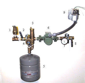
Zone Closed Loop
Control & Circulation Package
Less thermostat
- Pressure
relief valve
- Inlet
ball valve
- Automatic
air eliminator
- Inlet
water pressure regulator with bypass handle
for purge
- Expansion
tank
- Circulator
pump
- Pressure
& Temperature gauge
- Outlet
ball valve
- Relay
transformer package
R-C = 24 volts
R-G = Pump relay
|
 |
After
all piping and field connections are completed:
- Thread
hose adapter fitting in relief valve #1and run garden
hose to location of drain, close valve #2 and open
valve #8.
- Open
water inlet valve and allow pressure to build to
approx. 10/12 psi, check for system leaks.
- Slowly
open relief valve by raising handle on #1 and pressure
will bleed through hose to drain followed by water
flow as system fills. For faster fills, if desired,
handle can be raised on pressure regulator #4, this
will by-pass regulator. Caution must be used and
system monitored as not to exceed 30 psi. Water
will be running through distribution circuits and
out drain hose.
- Alternate
distribution circuits and allow to flow until all
air is removed and heat source is filled.
- Move
lever on pressure reducing valve #4 to normal operating
position, allow pressure to drop to 10/12 psi and
close relief valve #1. Remove adapter fitting from
relief valve #1 and pipe to floor or drain as code
requires.
- Open
valve #8, adjust thermostat and start system, the
automatic air vent #3, should eliminate any remaining
air with circulation. Balance water temperature
from heat source if required, the maximum temperature
should not exceed140¾, normal water temperatures
can vary from 100¾ to 125¾ dependent upon heating
loads.
Assembled control and circulation package as shown
is used for left to right supply flows. Right to left
flow is available with component adjustment.
|


